
ABS, Coupling & Uncoupling & Inspecting
6.3.1 – Trailers Required to Have ABS
All trailers and converter dollies built on or after March 1, 1998, are required to have ABS. However, many trailers and converter dollies built before this date have been voluntarily equipped with ABS.
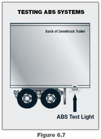
Trailers will have yellow ABS malfunction lamps on the left side, either on the front or rear corner. See Figure 6.7. Dollies manufactured on or after March 1, 1998, are required to have a lamp on the left side.
In the case of vehicles manufactured before the required date, it may be difficult to tell if the unit is equipped with ABS. Look under the vehicle for the ECU and wheel speed sensor wires coming from the back of the brakes.
6.3.2 – Braking with ABS
ABS is an addition to your normal brakes. It does not decrease or increase your normal braking capability. ABS only activates when wheels are about to lock up.
ABS does not necessarily shorten your stopping distance, but it does help you keep the vehicle under control during hard braking.
ABS helps you avoid wheel lock up. The computer senses impending lockup, reduces the braking pressure to a safe level, and you maintain control.
Having ABS on only the trailer, or even on only one axle, still gives you more control over the vehicle during braking.
When only the trailer has ABS, the trailer is less likely to swing out, but if you lose steering control or start a tractor jackknife, let up on the brakes (if you can safely do so) until you gain control.
When you drive a tractor-trailer combination with ABS, you should brake as you always have. In other words:
- Use only the braking force necessary to stop safely and stay in control.
- Brake the same way, regardless of whether you have ABS on the tractor, the trailer, or both.
- As you slow down, monitor your tractor and trailer and back off the brakes (if it is safe to do so) to stay in control.
Remember, if your ABS malfunctions, you still have regular brakes. Drive normally, but get the system serviced soon.
ABS won’t allow you to drive faster, follow more closely, or drive less carefully.
6.4 – Coupling and Uncoupling
Knowing how to couple and uncouple correctly is basic to safe operation of combination vehicles. Wrong coupling and uncoupling can be very dangerous. General coupling and uncoupling steps are listed below. There are differences between different rigs, so learn the details of coupling and uncoupling the truck(s) you will operate.
6.4.1 – Coupling Tractor-Semitrailers
Step 1. Inspect Fifth Wheel
- Check for damaged/missing parts.
- Check to see that mounting to tractor is secure, no cracks in frame, etc.
- Be sure that the fifth wheel plate is greased as required. Failure to keep the fifth wheel plate lubricated could cause steering problems because of friction between the tractor and trailer.
- Check if fifth wheel is in proper position for coupling.
- Wheel tilted down toward rear of tractor.
- Jaws open.
- Safety unlocking handle in the automatic lock position.
- If you have a sliding fifth wheel, make sure it is locked.
- Make sure the trailer kingpin is not bent or broken.
Step 2. Inspect Area and Chock Wheels
- Make sure area around the vehicle is clear.
- Be sure trailer wheels are chocked or spring brakes are on.
- Check that cargo (if any) is secured against movement due to tractor being coupled to the trailer.
Step 3. Position Tractor
- Put the tractor directly in front of the trailer. (Never back under the trailer at an angle because you might push the trailer sideways and break the landing gear.)
- Check position, using outside mirrors, by looking down both sides of the trailer.
Step 4. Back Slowly
- Back until fifth wheel just touches the trailer.
- Don’t hit the trailer.
Step 5. Secure Tractor
- Put on the parking brake.
- Put transmission in neutral.
Step 6. Check Trailer Height
- The trailer should be low enough that it is raised slightly by the tractor when the tractor is backed under it. Raise or lower the trailer as needed. (If the trailer is too low, the tractor may strike and damage the trailer nose; if the trailer is too high, it may not couple correctly.)
- Check that the kingpin and fifth wheel are aligned.
Step 7. Connect Air Lines to Trailer
- Check glad hand seals and connect tractor emergency air line to trailer emergency glad hand.
- Check glad hand seals and connect tractor service air line to trailer service glad hand.
- Make sure air lines are safely supported where they won’t be crushed or caught while tractor is backing under the trailer.
Step 8. Supply Air to Trailer
- From cab, push in “air supply” knob or move tractor protection valve control from the “emergency” to the “normal” position to supply air to the trailer brake system.
- Wait until the air pressure is normal.
- Check brake system for crossed air lines.
- Shut engine off so you can hear the brakes.
- Apply and release trailer brakes and listen for sound of trailer brakes being applied and released. You should hear the brakes move when applied and air escape when the brakes are released.
- Check air brake system pressure gauge for signs of major air loss.
- When you are sure trailer brakes are working, start engine.
- Make sure air pressure is up to normal.
Step 9. Lock Trailer Brakes
Pull out the “air supply” knob or move the tractor protection valve control from “normal” to “emergency.”
Step 10. Back Under Trailer
- Use lowest reverse gear.
- Back tractor slowly under trailer to avoid hitting the kingpin too hard.
- Stop when the kingpin is locked into the fifth wheel.
Step 11. Check Connection for Security
- Raise trailer landing gear slightly off ground.
- Pull tractor gently forward while the trailer brakes are still locked to check that the trailer is locked onto the tractor.
Step 12. Secure Vehicle
- Put transmission in neutral.
- Put parking brakes on.
- Shut off engine and take key with you so someone else won’t move truck while you are under it.
Step 13. Inspect Coupling
- Use a flashlight, if necessary.
- Make sure there is no space between upper and lower fifth wheel. If there is space, something is wrong (kingpin may be on top of the closed fifth wheel jaws, and trailer would come loose very easily).
- Go under trailer and look into the back of the fifth wheel. Make sure the fifth wheel jaws have closed around the shank of the kingpin.
- Check that the locking lever is in the “lock” position.
- Check that the safety latch is in position over locking lever. (On some fifth wheels the catch must be put in place by hand.)
- If the coupling isn’t right, don’t drive the coupled unit; get it fixed.
Step 14. Connect the Electrical Cord and Check Air Lines
- Plug the electrical cord into the trailer and fasten the safety catch.
- Check both air lines and electrical line for signs of damage.
- Make sure air and electrical lines will not hit any moving parts of vehicle.
Step 15. Raise Front Trailer Supports (Landing Gear)
- Use low gear range (if so equipped) to begin raising the landing gear. Once free of weight, switch to the high gear range.
- Raise the landing gear all the way up. (Never drive with landing gear only part way up as it may catch on railroad tracks or other things.)
- After raising landing gear, secure the crank handle safely.
- When full weight of trailer is resting on tractor:
- Check for enough clearance between rear of tractor frame and landing gear. (When tractor turns sharply, it must not hit landing gear.)
- Check that there is enough clearance between the top of the tractor tires and the nose of the trailer.
Step 16. Remove Trailer Wheel Chocks
Remove and store wheel chocks in a safe place.
6.4.2 – Uncoupling Tractor-Semitrailers
The following steps will help you to uncouple safely.
Step 1. Position Rig
- Make sure surface of parking area can support weight of trailer.
- Have tractor lined up with the trailer. (Pulling out at an angle can damage landing gear.)
Step 2. Ease Pressure on Locking Jaws
- Shut off trailer air supply to lock trailer brakes.
- Ease pressure on fifth wheel locking jaws by backing up gently. (This will help you release the fifth wheel locking lever.)
- Put parking brakes on while tractor is pushing against the kingpin. (This will hold rig with pressure off the locking jaws.)
Step 3. Chock Trailer Wheels
Chock the trailer wheels if the trailer doesn’t have spring brakes or if you’re not sure. (The air could leak out of the trailer air tank, releasing its emergency brakes. Without chocks, the trailer could move.)
Step 4. Lower the Landing Gear
- If trailer is empty, lower the landing gear until it makes firm contact with the ground.
- If trailer is loaded, after the landing gear makes firm contact with the ground, turn crank in low gear a few extra turns. This will lift some weight off the tractor. (Do not lift trailer off the fifth wheel.) This will:
- Make it easier to unlatch fifth wheel.
- Make it easier to couple next time.
Step 5. Disconnect Air Lines and Electrical Cable
- Disconnect air lines from trailer. Connect air line glad hands to dummy couplers at back of cab or couple them together.
- Hang electrical cable with plug down to prevent moisture from entering it.
- Make sure lines are supported so they won’t be damaged while driving the tractor.
Step 6. Unlock Fifth Wheel
- Raise the release handle lock.
- Pull the release handle to “open” position.
- Keep legs and feet clear of the rear tractor wheels to avoid serious injury in case the vehicle moves.
Step 7. Pull Tractor Partially Clear of Trailer
- Pull tractor forward until fifth wheel comes out from under the trailer.
- Stop with tractor frame under trailer (prevents trailer from falling to ground if landing gear should collapse or sink).
Step 8. Secure Tractor
- Apply parking brake.
- Place transmission in neutral.
Step 9. Inspect Trailer Supports
- Make sure ground is supporting trailer.
- Make sure landing gear is not damaged.
Step 10. Pull Tractor Clear of Trailer
- Release parking brakes.
- Check the area and drive tractor forward until it clears.
6.4.3 – Coupling a Pintle Hook
Step 1. Inspect Pintle Hook
- Before operating, check for worn, damaged, or missing parts, and make sure mount is secure.
- If the pintle hook is not secured to the mounting surface, the pintle hook could separate from the vehicle which, if not avoided, could result in death or serious injury.
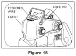
Step 2. Unlock Lock Pin and Open Latch
- Unlock and remove the tethered lock pin, if applicable (Figure 16).
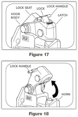
- Lift the lock handle away from the vehicle until the lock clears the lock seat on the hook body.
- Open the latch by rotating the latch assembly up toward the vehicle until the latch is in its most upright position, then release the lock handle. (Figure 17 and 18)
Step 3. Lower Drawbar into Place
- Position the drawbar eye over the horn of the pintle hook and lower it into place.
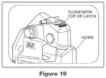
Step 4. Lock Pintle Hook
- Push the latch closed. When correctly locked, the lock handle will rotate and move up until it is flush with the top of the latch (Figure 19).
- Insert the tethered lock pin through the latch and lock holes, and close the tethered wire lock pin, if applicable (Figure 16).
- Failure to correctly lock the latch can result in separation of the trailer and vehicle which, if not avoided, could result in death or serious injury.
6.4.4 – Uncoupling a Pintle Hook
Step 1. Park on Level Surface
- Park the trailer on a firm level surface and block trailer tires.
Step 2. Disconnect Electrical Connector, Breakaway Brake Switch and Safety Chains
- Disconnect electrical connector.
- Disconnect breakaway brake switch lanyard.
- Disconnect safety chains from tow vehicle.
Step 3. Unlock the Coupler
- Unlock the coupler and open it.
Step 4. Check Ground Surface for Correct Support
- Before extending jack, make certain the ground surface below the jack pad will support the tongue load.
Step 5. Rotate Jack Handle
- Rotate jack handle to extend the jack and transfer the weight of the trailer tongue to the jack.
Step 6. Raise Trailer Coupler
- Raise the trailer coupler above the tow vehicle hitch.
Step 7. Drive Forward
- Drive tow vehicle forward.
6.4.5 – Coupling a Drawbar
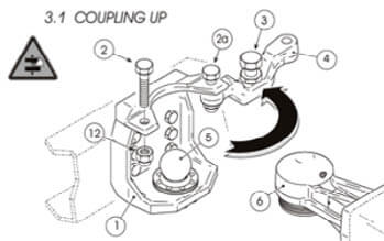
Step 1. Remove Safety Lock screw and Rotate Safety Cover Bar
- Remove safety lock screw (2), recover and keep the relative self-locking nut (12) aside then also loosen safety lock screw (2a) and turn out the adjustment screw (3) by at least five turns.
- Rotate the safety cover bar (4) outwards so that it is completely open.
Step 2. Reverse Truck
- Reverse truck very slowly until the ball cup drawbar eye (6) is in position exactly above the drawbar coupling ball (5).
Step 3. Lower the Drawbeam
- Lower the drawbeam until the ball cup drawbar eye (6) lies completely covering the drawbar coupling ball (5).
Step 4. Rotate the Safety Cover Bar
- Rotate the safety cover bar back inwards (4) and fit in safety lock screw (2) together with its self-locking nut.
- Tighten in both the lock screws (2, 2a) together with their relative self-locking nuts (12, 12a) at a 350 to 400 Nm torque wrench setting.
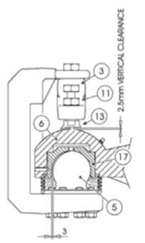
Step 5. Adjust the Adjustment Screw
- Adjust the adjustment screw (3) until a 0.3 – 0.5 mm vertical clearance between the guard disk (13) and the ball cup (6) is reached. Lock setting with counter nut (11).
- In the event that the safety cover bar (4) will not perfectly lodge into its seating appropriately, travel is strictly forbidden.
Step 6. Protect Coupling Ball and Anchor Edge onto Ball
- Protect the part that is still visible of the coupling ball (5) with the rubber dust proof bellows protection cover (7). Accurately anchor the edge directly onto the ball itself.
Step 7. Lubricate the Drawbar Eye
- Lubricate the inside of the drawbar eye ball cup (6) directly through the grease nipple (18).
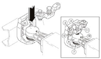
6.4.6 – Uncoupling a Drawbar
Step 1. Turn Trailer Brake On
- Make sure that the trailer brake is on.
Step 2. Remove Cover and Loosen Screws
- Remove the rubber dust proof bellows protection cover (7).
- Loosen the adjustment screw (3) and the counter nut (11).
- Loosen safety lock screw (2a) and remove safety lock screw (2) together with its self-locking nut (12).
Step 3. Rotate Safety Cover Bar and Lift Trailer Drawbeam
- Rotate the safety cover bar (4) outwards so that it is completely open.
- Lift the trailer drawbeam until the drawbar coupling ball (5) is fully visible, then travel forward with the trailer very slowly.
- Rotate the safety cover bar inwards (4) until it lodges back in its housing.
Step 4. Lock Safety Screw and Tighten Self-Locking Nut
- Fit in safety lock screw (2) and tighten in self-locking nut (12).
6.4.7 – Coupling a Gooseneck Hitch
- If you are hooking up a Gooseneck or a fifth wheel hitch, the procedure is a little different from a receiver and ball, but it is not more difficult.
Step 1. Open the Latch and Lubricate the Gooseneck Ball
- Open the clamp latch on the Gooseneck coupler.
- Make sure that the Gooseneck ball is properly lubricated.
Step 2. Position Coupler and Latch the Clamp
- Position the trailer’s coupler directly over the ball and lower the Gooseneck trailer into position and latch the clamp.
Step 3. Attach Safety Chains
- Attach your safety chains. Remember that all trailers are required by law to have safety chains.
Step 4. Connect Trailer Light Wiring
- Connect your trailer light wiring to your vehicle’s connector.
- Check all of your lights, including your brake lights.
Step 5. Lower and Stow the Trailer Jacks
- Completely lower and stow the trailer jacks, allowing the weight to settle onto the tow vehicle.
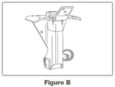
6.4.8 – Uncoupling a Gooseneck Hitch
Step 1. Remove Safety Pin and Clip
- Simply remove safety pin and clip.
Step 2. Rotate Handle and Raise Trailer Off Ball
- Rotate handle to this position (Fig. B) and raise trailer off ball. Coupler will return to load position automatically.
Step 3. Install Safety Pin and Clip
- Install safety pin and clip. (Fig. B)
6.5 – Inspecting a Combination Vehicle
Use the seven-step inspection procedure described in Section 2 to inspect your combination vehicle. There are more things to inspect on a combination vehicle than on a single vehicle. (For example, tires, wheels, lights, reflectors, etc.) However, there are also some new things to check. These are discussed below.
6.5.1 – Additional Things to Check During a Walk-around Inspection
Do these checks in addition to those already listed in Section 2.
Coupling System Areas
- Check fifth wheel (lower).
- Securely mounted to frame.
- No missing or damaged parts.
- Enough grease.
- No visible space between upper and lower fifth wheel.
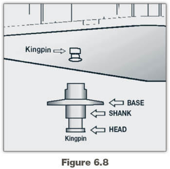
- Locking jaws around the shank, not the head of kingpin. See Figure 6.8.
- Release arm properly seated and safety latch/lock engaged.
- Check fifth wheel (upper).
- Glide plate securely mounted to trailer frame.
- Kingpin not damaged.
- Air and electric lines to trailer.
- Electrical cord firmly plugged in and secured.
- Air lines properly connected to glad hands, no air leaks, properly secured with enough slack for turns.
- All lines free from damage.
- Sliding fifth wheel.
- Slide not damaged or parts missing.
- Properly greased.
- All locking pins present and locked in place.
- If air powered–no air leaks.
- Check that fifth wheel is not so far forward that tractor frame will hit landing gear, or the cab hit the trailer, during turns.
Landing Gear
- Fully raised, no missing parts, not bent or otherwise damaged.
- Crank handle in place and secured.
- If power operated, no air or hydraulic leaks.
6.5.2 – Combination Vehicle Brake Check
Do these checks in addition to Section 5.3: Inspecting Air Brake Systems.
The following section explains how to check air brakes on combination vehicles. Check the brakes on a double or triple trailer as you would any combination vehicle.
Check That Air Flows to All Trailers. Use the tractor parking brake and/or chock the wheels to hold the vehicle. Wait for air pressure to reach normal, then push in the red “trailer air supply” knob. This will supply air to the emergency (supply) lines. Use the trailer handbrake to provide air to the service line. Go to the rear of the rig. Open the emergency line shut-off valve at the rear of the last trailer. You should hear air escaping, showing the entire system is charged. Close the emergency line valve. Open the service line valve to check that service pressure goes through all the trailers (this test assumes that the trailer handbrake or the service brake pedal is on), and then close the valve. If you do NOT hear air escaping from both lines, check that the shut-off valves on the trailer(s) and dolly(ies) are in the OPEN position. You MUST have air all the way to the back for all the brakes to work.
Test Tractor Protection Valve. Charge the trailer air brake system. (That is, build up normal air pressure and push the “air supply” knob in.) Shut the engine off. Step on and off the brake pedal several times to reduce the air pressure in the tanks. The trailer air supply control (also called the tractor protection valve control) should pop out (or go from “normal” to “emergency” position) when the air pressure falls into the pressure range specified by the manufacturer. (Usually within the range of 20 to 45 psi.)
If the tractor protection valve doesn’t work right, an air hose or trailer brake leak could drain all the air from the tractor. This would cause the emergency brakes to come on, with possible loss of control.
Test Trailer Emergency Brakes. Charge the trailer air brake system and check that the trailer rolls freely. Then stop and pull out the trailer air supply control (also called tractor protection valve control or trailer emergency valve), or place it in the “emergency” position. Pull gently on the trailer with the tractor to check that the trailer emergency brakes are on.
Test Trailer Service Brakes. Check for normal air pressure, release the parking brakes, move the vehicle forward slowly, and apply trailer brakes with the hand control (trolley valve), if so equipped. You should feel the brakes come on. This tells you the trailer brakes are connected and working. (The trailer brakes should be tested with the hand valve but controlled in normal operation with the foot pedal, which applies air to the service brakes at all wheels.)
Test Your Knowledge
- What might happen if the trailer is too high when you try to couple?
- You should look into the back of the fifth wheel to see if it is locked onto the kingpin. True or False?
- To drive you need to raise the landing gear only until it just lifts off the pavement. True or False?
- How do you know if your trailer is equipped with antilock brakes?
- Which shut-off valves should be open and which closed?
- How can you test that air flows to all trailers?
- How can you test the tractor protection valve?
These questions may be on your test. If you can’t answer them all, re-read subsections 6.3, 6.4 and 6.5.